 |
| May 14, 2024 | Volume 20 Issue 18 |
Designfax weekly eMagazine

Archives
Partners
Manufacturing Center
Product Spotlight
Modern Applications News
Metalworking Ideas For
Today's Job Shops
Tooling and Production
Strategies for large
metalworking plants
8 top ways to wreck your coupling-driven system
Keeping a servo-driven system running at peak efficiency is no simple feat. Misunderstanding performance criteria such as misalignment, torque, or revolutions per minute (rpm) can be all it takes to cause a critical and costly failure. Engineers at Ruland Manufacturing Co. have compiled the eight best ways to consistently sabotage or damage your coupling-driven system -- and how to avoid these pitfalls in the future.
1. Choosing the wrong coupling
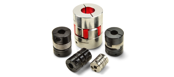
Servo couplings from Ruland (from center clockwise): jaw coupling, oldham coupling, beam coupling, disc coupling, bellows coupling.
Unsurprisingly, one of the most effective and common ways to wreck your system is by selecting the wrong coupling. There are many factors a design engineer must keep in mind to avoid coupling failure. Balancing criteria such as torque, rpm, shaft size, tolerances, operating environment, and misalignment is paramount to selecting the right coupling.
2. Not identifying misalignment
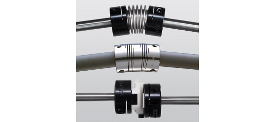
Working properly: Three types of Ruland couplings on shafts (from top to bottom): bellows coupling, beam coupling, oldham coupling.
Most servo applications have one or more forms of misalignment. This is a primary concern, since misalignment can cause stress to system components such as bearings, not just to the coupling itself. Misalignment is often caused by a tolerance mismatch from the driving side of a system to the driven side. This can be caused by a variety of factors, including parts from different manufacturers, inaccuracies in assembly, system/motor movement during operation, system component wear, poor mounts, and thermal shaft expansion.
Each coupling style can accommodate different amounts of misalignment. Designers must understand the nature of an existing misalignment to determine if a high-misalignment coupling is needed at the expense of factors such as torque, or if corrective system adjustments are necessary before selecting a coupling.
3. Exceeding rpm recommendation
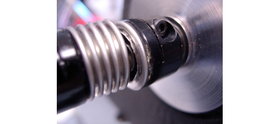
This bellows coupling has failed in a deep convolution closer to one hub than the other and represents what may occur in a misalignment situation. This type of failure can occur with an excessive degree of misalignment exceeding coupling design limits, or when the coupling is improperly installed and the misalignment (again within specifications) is not uniformly distributed across the bellows.
System requirements determine speed, and in precision-driven servo systems it is possible to have speeds of 2,000, 5,000, 10,000, or even 25,000 rpm. Unfortunately, not every coupling can handle higher speeds, even if they are otherwise a perfect fit for the system. Exceeding the manufacturer's rpm rating can cause coupling failure or damage to system components.
Even if the coupling is rated for high rpm, greater speeds increase the effects of misalignment. For example, a disc coupling might accommodate very slight angular misalignment at its maximum rated speed of 10,000 rpm without adverse effects on the coupling or system components, but it will cause damage at a speed of 15,000 rpm with the same misalignment. Designers must know the maximum operating speed the coupling will experience to select the right one. It is also important to understand how manufacturers determine ratings -- using performance factors in isolation or everything at max.
4. Not considering coupling wear

Failed spider coupling.
Couplings are designed to be the wear element in most systems to protect more expensive components such as bearings and motors. Each coupling wears differently and will fail in a different way. Beam and bellows couplings will completely fail, stopping power transmission, when they reach the end of their service life. Disc, jaw, and oldham couplings will lose zero-backlash, but still transmit motion. Depending on the application requirements, one of these wear types may not be desirable.
Additionally, designers must consider if the coupling requires maintenance or replacement when reaching the end of its service life. Beam, bellows, and disc couplings are maintenance-free and require complete replacement after a failure, whereas oldham and jaw coupling performance can be restored by replacing the insert after failure. During the testing phase, designers can better understand the service life of the coupling and give a recommended maintenance schedule to best avoid unplanned downtime.
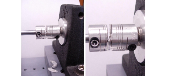
5. Installing the coupling incorrectly
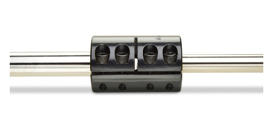
Rigid coupling on a shaft.
There is no faster way to undo the work of selecting the perfect coupling and optimizing system parameters than installing it incorrectly. For example, uneven torquing of the screws, incorrect shaft penetration, installing off-center, and compressing or stretching the coupling can lead to a failure or premature wear of sensitive system components. The safest option is to follow the manufacturer installation instructions, especially when accompanied by videos.
6. Buying generic couplings
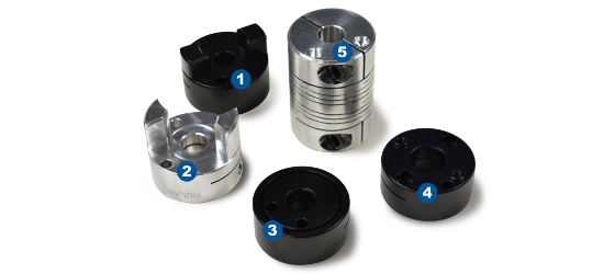
Balanced holes for a balanced design. 1: oldham coupling, 2: jaw coupling, 3: bellows coupling, 4: disc coupling, 5: beam coupling.
Not all couplings are created equal, or for the same purposes. Some couplings are manufactured with common specifications, tolerances, and designs, such that they are nearly indistinguishable from many others on the market. This may be suitable for systems with limited performance requirements, but precision systems often require or benefit from couplings with additional capabilities.
For example, balanced designs are not the industry standard for most couplings. In an application like printing, the reduced vibration afforded by a balanced design is a necessity -- less precise couplings would cause banding and expensive waste or downtime. The five servo couplings in the picture above all have balanced holes for a balanced design.
The Ruland Youtube channel is filled with informative videos like this one.
7. Selecting the coupling late in the design process
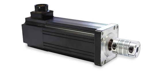
Beam coupling on motor.
Far too often, motion control couplings are selected late in the design process. This can limit which coupling is used in the system and the performance it delivers. For example, a system requiring high torque and speed may need to use a disc coupling, but ultimately have an envelope that is too small to fit a double-disc type, forcing the designer to select a single-disc type. While it may meet the speed and torque requirements, single-disc couplings cannot accommodate parallel misalignment, meaning that the system will require greater precision during installation to eliminate the chance of parallel misalignment, likely adding cost and complication.
Considering the coupling earlier in the design process would have likely eliminated this issue, saving time and money. To make the design process easier, manufacturers may have CAD, detailed product information, and technical support available on their website.
The Ruland Youtube channel is filled with informative videos like this one.
8. Failing to test
This beam coupling has failed near the center and represents what may occur in a torque overload condition. A torque in excess of the coupling design limits was applied to illustrate this example. Beam coupling failure may also occur in applications with parallel misalignment, because the single beam must bend in two different directions simultaneously, creating larger stresses in the coupling that could cause premature failure.
One of the first rules of system design is "always test." While everything may look correct in the design, it is hard to determine suitability until the coupling is run under common-use conditions. Extensive testing prior to use in live systems can help maximize coupling and system performance. Manufacturers can assist in the design process with technical support and by providing product samples to ensure proper coupling selection.
The Ruland Youtube channel is filled with informative videos like this one.
Check out ruland.com for all of your coupling needs, or dial 1-508-485-1000 to talk to a Ruland rep. Please tell them you saw Ruland in Designfax.
Source: Ruland Manufacturing Co.
Published May 2024
Rate this article
View our terms of use and privacy policy